From a Simple Thermostat to a Multi-Zone System
We’ve already published a project in the Home Automation section describing how to build an internet-controlled thermostat for a heating boiler. That system offered basic functionality — turning the heat on and off at certain temperatures, controlling just one zone.
This time, we’ll see how to configure a smart thermostat system for your boiler that can manage two or more zones. The system can be controlled from your phone via a dedicated app, or using a touch display mounted in accessible spots around the house. All these functions are built with Shelly automation components, just like in the single-zone thermostat project.
I’m a big fan of Shelly products. I’ve been using them for years, and they’ve proven to be reliable, well-designed, and constantly evolving. The company frequently launches new products, provides a solid app with full functionality even in the free plan, and keeps prices reasonable.
Automation Scenario: Two-Zone Temperature Control
The goal is to control ambient temperature independently in two zones — for example, the ground floor and the upper floor of a house.
The heating system consists of:
- a gas boiler,
- a distributor for each zone,
- and a dedicated circulation pump for each zone.
Components Used in the Project
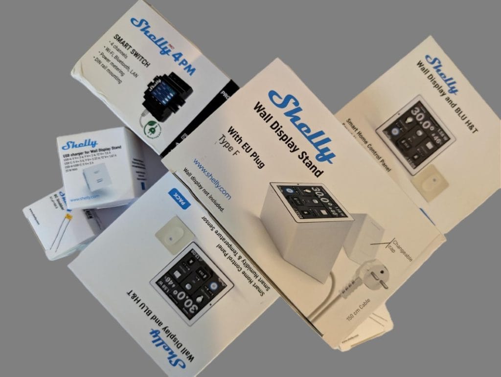
- 2× Shelly Wall Display with Blu H&T temperature and humidity sensor – for reading temperature values in each zone and controlling the respective thermostat
- 2× RC Snubber – protects the Shelly Pro 4PM from surges caused by the pumps
- 1× Shelly Pro 4PM – the main component of the system, with four combined outputs (up to 40 A total), used to control the two circulation pumps
- Shelly Wall Display Stand – a dedicated stand for installing one of the displays, as an alternative to wall mounting
- Shelly USB Charger – a 20 W charger with USB-C and USB-A outputs, useful when using the display stand and for powering other devices
Connections and the Role of Each Component
Shelly Pro 4PM – The Heart of the System
This is the core component, as it powers and controls both heating zones. The Shelly Pro 4PM includes four outputs (O), four control inputs (S), power terminals (L and N), and an Ethernet port. It can connect either via Wi-Fi or Ethernet cable.
From my testing, I strongly recommend using a wired connection, since the device’s Wi-Fi signal is relatively weak, which can cause control delays.
In this project, the Shelly Pro 4PM connects to mains power through the L and N terminals and uses two of its outputs (O1 and O2) to power and control the two pumps. The neutral wires of the pumps are connected directly to the power line.
The switch-type inputs (S) are not used, because the system is controlled entirely through the Shelly app, with no physical connections between components.
Shelly 1 – Boiler Control
Heating boilers are typically controlled through a simple on/off contact. For this reason, they can’t be connected directly to the Shelly Pro 4PM, whose outputs carry live voltage when activated.
To handle this, we use a Shelly 1, which acts as a basic relay with on/off functionality. It’s powered from the mains, and the control logic is configured via the Shelly app.
RC Snubber – Pump Protection
According to Shelly Pro 4PM specifications, using an RC Snubber is recommended for inductive loads such as pumps. The two RC Snubbers should be installed as close as possible to the pumps.
They’re connected using Wago connectors, and polarity doesn’t matter.
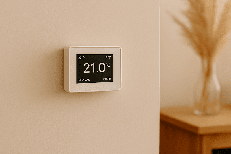
Shelly Wall Display – Local Interface and Thermostat
The Shelly Wall Display connects directly to mains power — no external power adapter is needed. It can be mounted in a standard wall box or using the dedicated stand. The electrical connection only requires live and neutral wires (L and N).
The O and SW outputs are not used in this setup, since the control is fully network-based. The Wall Display includes an internal relay, but it’s not used in this project.
Software Configuration for the Zonal Thermostats
Configuration in the Shelly app happens in two steps.
Each Wall Display includes an integrated software thermostat, which can be activated from the device menu. It can be configured to read temperature data from the Blu H&T sensor and to control a target device — in our case, one of the O1 or O2 outputs of the Shelly Pro 4PM.
Each of the four outputs on the Shelly Pro 4PM appears in the app as a separate device. The limitation is that a thermostat can only control one target device, meaning we can’t include both the Shelly 1 (for the boiler) and Shelly Pro 4PM outputs in the same command set.
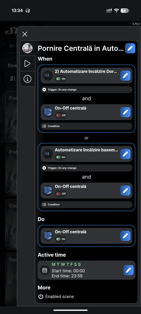
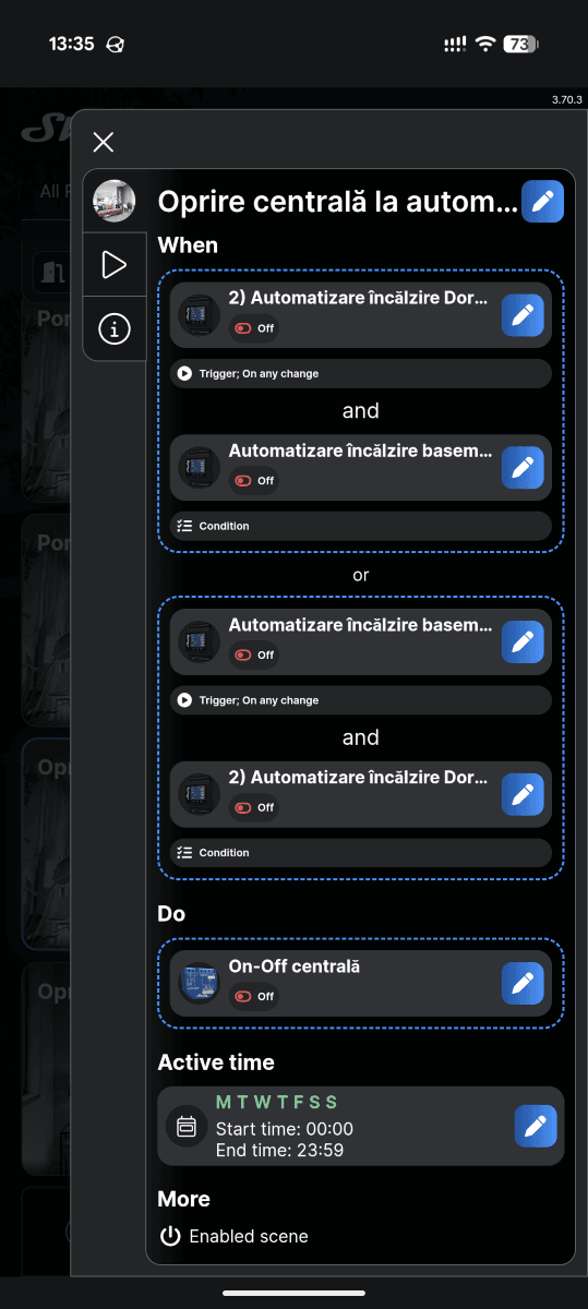
Logical Scenes: Controlling the Boiler Based on Zone Activity
To overcome this limitation, we use the Logical Scenes feature in the Shelly app.
Here’s the logic:
- If at least one of the outputs (O1 or O2) is active, that means at least one thermostat has triggered heating → the boiler should turn on.
- If both outputs are off, both zones have reached the desired temperature → the boiler should turn off.
- (Optional) Check the current state of the boiler before sending the on command to avoid redundant operations. In practice, if the boiler relay is already active, sending another “on” command doesn’t change anything.
This two-zone control setup can easily be extended to more zones by adding components and updating the logical scenes.
Connection Summary and Operating Logic
To give a clear overview, the diagram below (conceptually) outlines the main connections between the system components and how they interact within the automation setup.
1. Control Panel – The Heart of the System
Shelly Pro 4PM
- Powered directly from the mains via terminals L (Live) and N (Neutral).
- Connected to the local network via Ethernet cable for maximum stability.
- Output O1 powers the pump for Zone 1, while O2 powers the pump for Zone 2.
- Outputs O3, O4 and inputs S1–S4 remain unused in this configuration.
Shelly 1
- Also powered from the same mains supply (L and N).
- Terminals I and O act as a dry contact (no voltage) and connect directly to the boiler’s thermostat terminals (TA / T1–T2).
2. Heating Zones
Circulation Pumps
- Each pump receives its live wire from the corresponding output on the Shelly Pro 4PM (O1 or O2).
- The neutral of both pumps connects to the main neutral line of the electrical network.
- Both pumps should also be connected to earth (PE) if available.
RC Snubber
- One RC Snubber is installed per pump, in parallel between live and neutral.
- For best protection, it should be mounted as close as possible to the pump.
3. User Interface and Sensors
Shelly Wall Display (×2)
- Each display is installed in a wall box and powered directly from the mains (L and N).
- The O and SW outputs are not used in this project.
- Each communicates via Bluetooth with its paired Shelly Blu H&T sensor in the same zone to measure temperature.
Logical Communications (via Wi-Fi / Cloud)
- The software thermostat within each Wall Display controls the corresponding Shelly Pro 4PM output (O1 / O2).
- Logical scenes in the Shelly app manage the Shelly 1 boiler relay:
- If O1 or O2 is active → the boiler turns on.
- If O1 and O2 are both off → the boiler turns off.
Recommendations and Best Practices from Testing
The thermostat function of the Shelly Wall Display is just one of its many capabilities — it can also be used for other home automation tasks.
All Shelly products are compatible with the open-source Home Assistant ecosystem, for those who want unified control of all their smart devices.
During testing, I noticed that the Shelly Pro 4PM is less stable over Wi-Fi compared to other Shelly devices. This is likely due to surrounding power cables interfering with the signal.
I recommend Ethernet connection, as Wi-Fi mode caused several-minute delays in executing commands, making the system nearly unusable.
Once connected via Ethernet, everything worked instantly and perfectly as expected.